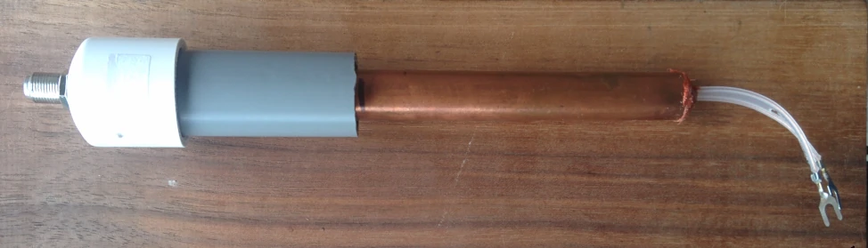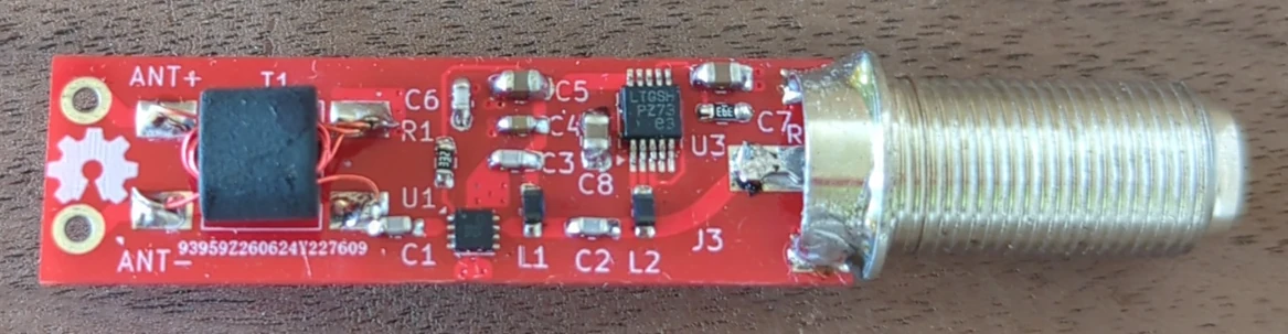
I've been using Grey-Hoverman antennae since they first came out in 2008. I had one in my attic with a Kitztech KT-200-COAX low noise amplifier close by. Eventually I moved to a different location and put the antenna and amp outside. My home made waterproofing for the amp eventually failed and so did the amp shortly after. I don't think Kitztech had the waterproof option when I bought it. So do I buy another Kitztech or make my own? I wanted an amp that...
About the same time my Kitztech died, the QPL9547 LNA MMIC came out. The QPL9547 is a high-linearity, ultra-low noise amplifier. Some specs...

The amp is powered by DC over the coax cable. L2 passes the DC into an ultra low noise linear regulator U3 set at 4v. Inductors are not perfect and have some capacitance. This is especially a problem at higher frequency as the capacitance couples the high frequency "eating" some of the signal. I used a 150nH inductor with the highest self-oscillating frequency (lowest capacitance) I could find. Why 150nH and not the lower value from the eval board? The eval board is setup for higher frequencies than UHF. 150nH gives 470Ω of reactance (XL) at 500Mhz. A smaller inductor would eat more of the UHF signal.
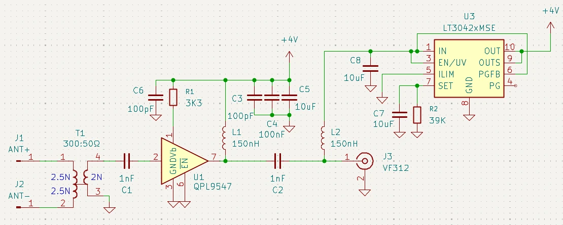
Regulator U3 is needed for long coax runs that have some DC drop. C3, C4 and C5 provide supply filtering. R2 sets the regulator's output voltage. L1 is another 150nH inductor which supplies the regulated 4v to the QPL9547 amp IC. The QPL9547 amp IC requires DC blocking capacitors C1 and C2 at it's input and output. C1 and C2 are 1nF and have a reactance of 0.3Ω at 500Mhz
Kicad Project files (version 9 or greater) can be cloned via git. They include gerbers ready for ordering if you don't want to use the PCB in the Dirty PCB store. The impedance controlled traces are optimized for 0.6mm thickness FR4.
git clone https://codeberg.org/jbagg/Super-TV-RF-Signal-Amp.git
This amp can be used with any 300Ω antenna and also with 50Ω cabling by installing a different output connector such as a 50Ω BNC.
The QPL9547's input and output are internally matched to 50Ω. For the input we need to match the antenna's 300Ω to 50Ω. This is a 6:1 impedance ratio, which works out close to a 5 turns to 2 turns ratio transformer. (5^2 / 2^2 = 25 / 4 = 6.25) I was not able to source a balun transformer like this so I wound my own using this winding pattern.
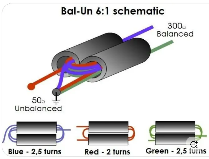
I tried two different K1 material type core sizes. A larger using 30awg wire and a smaller using 38awg wire. The idea with the smaller one was to reduce the surface area of the wires which should reduce capacitance. However there was no difference when I measured the gain of each of them. I wasn't sure if the K1 core material was the best to use so I also tried winding one using a core from an off the shelf 4:1 balun MABA-009488-61HWCA but again it measured the same. I also tried using an unmodified off the shelf 4:1 balun. The impedance match should not be as good so I expected it to have a lower signal. Below 550Mhz is was the same and above 550Mhz it was only down by about 1-2dB. Maybe my balun winding skills have room for improvement. If you don't want to wind your own, the MABAES0031 is a good choice. The newest version of the PCB has a dual footprint for both the MABAES0031 and wind your own.
| Part Number | AL | Dimensions h x w x l | ||
| 1 | B62152A0007X001 | 140nH | 6.2 x 7.3 x 4.2mm | 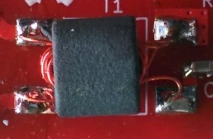 |
| 2 | B62152A0008X001 | 60nH | 2.5 x 3.6 x 2.1mm | 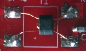 |
| 3 | MABA-009488-61HWCA | 1.5 x 1.8x x3.5mm | 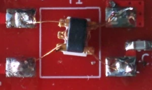 | |
| 4 | MABAES0031 | Stock 4:1 | 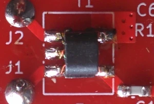 |
Through experimentation it was found that not grounding the centre tap on the balun caused a 5dB drop on frequencies > 550Mhz. Both the stock 4:1 balun and the custom 6:1 balun behaved similar when the centre tap was not grounded.
So how do we match to a 75Ω cable? We don't! The energy loss between a 50Ω to 75Ω mismatch is only 4%. I looked at a few 50Ω to 75Ω transformers and their insertion loss was about the same or slightly higher than the 4% energy loss. Using a transformer would have been worse or had no effect.
During testing I noticed the amplifier could start oscillating between 1.5Ghz and 1.7Ghz. When oscillating, the signal gain would drop 3-4dB, the amp IC's current would increase 25-100% and there was a bunch of sub harmonics. I noticed that if I touched specific points along the 10cm twin-lead feedline oscillation would stop. The spacing of these points was about 1/2λ of the oscillating frequency. I also noticed I could invoke oscillation if I touched 1/2 way between the points that would usually stop it. Touching the ground on the coax connector on the PCB output could invoke oscillation as well. Eventually I realized that the 10cm twin-lead feedline was picking up some of the output signal in the coax as a feedback path. I added a 1/2 copper tube around the 10cm twin-lead feedline and I haven't been able to invoke oscillation since. The 1/2 copper tube does want to be soldered directly to the ground plain on the PCB. I tried connecting the copper tube to the same point as the coax ground connection and the amp could still sometimes be put into oscillation. The copper tube did not appear to effect signal strength.
These measurements were taken at ground level using a Grey-Hoverman antenna, first with a 300Ω to 75Ω Balun and then with the Super Amp
| 485Mhz | 491Mhz | 581Mhz | 593Mhz | 605Mhz | |
| Pass Through | -75dB | -73.2dB | -59.4dB | -77.7dB | 76.9dB |
| Amp | -49dB | -47dB | -32.6dB | -53.6dB | -52.2dB |
| Gain | 26dB | 26.2dB | 26.8dB | 24.1dB | 24.7dB |
These measurements were taken with the super amp attached to a Grey-Hoverman antenna 8.3m off the ground. Ground elevation 107m above sea level. Mostly overcast day. Connection to amp / antenna is with 11m of RG-59 cable. The Spectrum Analyzer was set to BW=30Khz, VBW=30Khz, 1.05s sweep time, 30Mhz span.
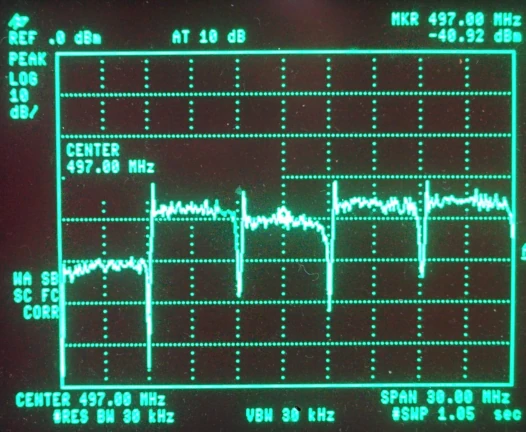 |
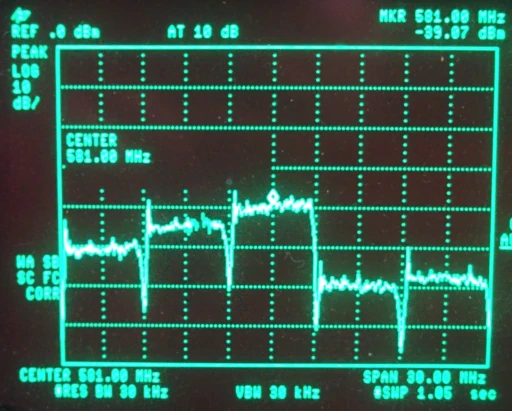 |
||||||||||||||||||||||||||||||||||||||||||||||||||||||||||||||||||||||||||||||||||||
|
|
This BOM is for the amp circuit board only. It does not include the housing or the T power injector. There are seperate pages with their own BOMs for the housing and T power injector.
The circuit board can be directly ordered from the Dirty PCB store here.
| Item | Reference | Part Number | Value | |
| 1 | U1 | QPL9547TR7 | QPL9547 | |
| 2 | U3 | LT3042EMSE#TRPBF | LT3042 | |
| 3 | L1,L2 | 7447610215 | 150nH | 603 |
| 4 | C1,C2 | 1nF COG | 603 | |
| 5 | C5,C7,C8 | 10uF | 805 | |
| 6 | C3,C6 | 100pF COG | 603 | |
| 7 | C4 | 100nF | 603 | |
| 8 | R1 | 3.3KΩ | 603 | |
| 9 | R2 | 39KΩ | 603 | |
| 10 | J3 | VF312 | 75Ω F Connector | |
| 11 | T1 | B62152A0007X001 | 140nH | K1 Core for 6:1 Balun |
| 12 | Alt T1 | MABAES0031 | 4:1 | Alternate T1. |