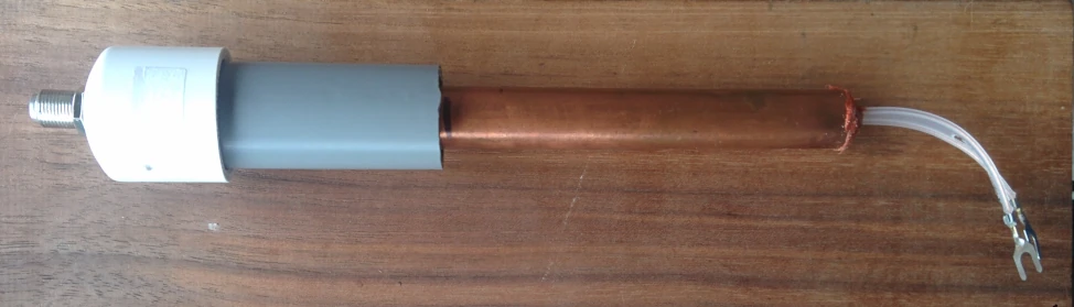
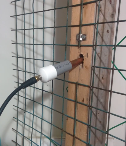
| Description | Quantity | Part Number | URL |
| 1/2" Copper pipe | 1 | 14cm (5-1/2") length | |
| Solder Wick | 1 | example 80-2-5 | Digikey |
| 3/4" PCV pipe Schedule 40 | 1 | 8cm length | |
| 3/4" PVC End Cap | 1 | R447-007 | On Website |
| 3/8" O-ring | 1 | #008 | ID=0.375" CS=0.070" |
| 5/8" O-ring | 2 | #114 | ID=0.625" CS=0.103" |
| 300Ω twin lead | 1 | Amazon |
Step 1 - Cut a piece of 1/2" copper tube to a length of 14cm (5-1/2")
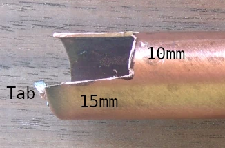
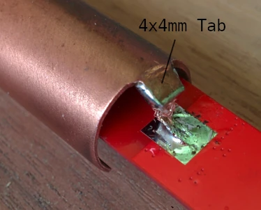
Step 2 - Remove about 4mm (5/32") from one end of the copper tube most of the way around so that it leaves a 4mm square tab stuck out. This is to create a bit of a thermal relief to solder on a short piece of solder wick.
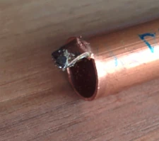
Step 3 - Cut a 15mm (5/8") length of solder wick and solder about 4mm of one end onto the tube. In a later step the other end of the solder wick will be soldered to the circuit board's GND pad. This creates a mechanical disconnect between the tube and the PCB. Do not make longer than 15mm or the amp will oscillate!
Step 4 - Optionally cut out a notch 180 degrees opposite to the 4x4mm solder tab, aprox 15mm (5/8") deep and 10mm (3/8") on the perimeter. This makes it possible to unsolder the amplifier from the twin lead if you want to remove the amplifier in the future to do experiments with different amplifier configurations. Skip this step if you don't plan on doing experiments with different amplifier configurations.
Step 5 - Cut a piece of the 300Ω twin lead 20cm (7-7/8") in length and strip the ends. Solder the 300Ω twin lead onto the amp.
Step 6 - Cut two pieces of cardboard 12mm (15/32") wide by 12cm (4-3/4") long. These will be inserted in the tube sandwiching the twin lead helping to keep it centred in the tube.
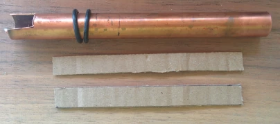
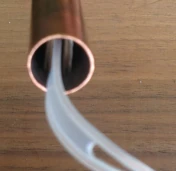
Step 7 - Sandwich the twin lead with the two pieces of cardboard. Insert the amp through the copper tube starting from the end that does not have the tab. Push the amp all the way through until the GND pad on the bottom of the PCB lines up with the tube's tab / solderwich.
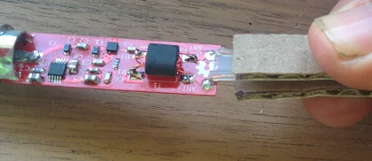
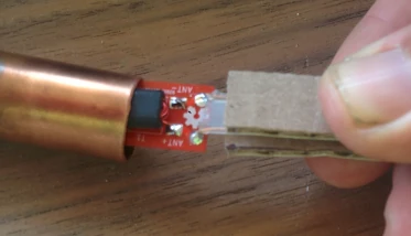
Step 8 - Solder the solderwick to the GND pad on the PCB.
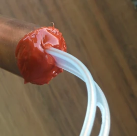
Step 9 - Apply a good amount of silicon to the end of the tube where the twin lead exits to form a watertight seal. Use a silicon that is compatible with copper. Regular silicon will react with the copper and not cure properly. I recommend Permatex Red RTV.
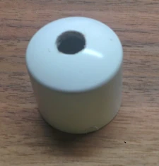
Step 10 - Drill a 3/8" hole in the centre of the 3/4" PVC end cap as shown.
Step 11 - Cut a piece of 3/4" pipe 8cm in length.
Step 12 - Glue the End cap onto the 3/4" PCV pipe. Make sure it slides all the way down.
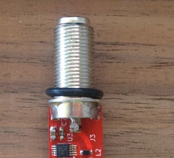
Step 13 - Slide the small o-ring onto the coax connector on the PCB as shown.
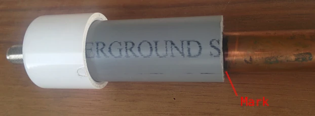
Step 14 - Slide the amp + copper pipe assembly into the 3/4" PVC as shown and mark the end of the 3/4" PVC on the 1/2" copper pipe. This will help when assembling with o-rings in the next step.
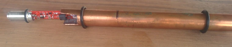
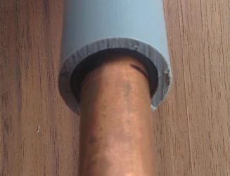
Step 15 - Remove the amp + copper pipe assembly and slide on the 2 larger o-rings onto the 1/2" copper pipe as shown. Aprox location only.
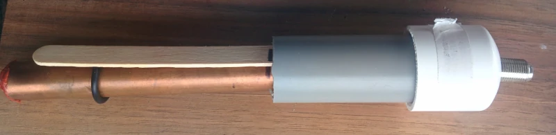
Step 16 - Mark a popsicle stick 2 to 2.5cm (3/4" to 1") from the end.
Step 17 - Again slide the amp + copper tube assembly into the 3/4" PVC. The o-ring will want to resist. Use the popsicle stick to work down the o-ring until the mark on the popsicle stick is at the end of the 3/4" PVC pipe. Double check the end of the 3/4" pipe is on the mark on the 1/2" copper pipe.
Step 18 - Next slide the 2nd o-ring up and insert it into the 3/4" pipe so that it is flush or slightly recessed. Again double check the end of the 3/4" pipe is on the mark on the 1/2" copper pipe. The outer o-ring provides the seal and the inner o-ring provides some mechanical strength to keep the 1/2" copper pipe and 3/4" PVC pipe moving together without straining the wires and solderwick.
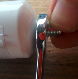
Step 19 - Tighten the nut being careful to only hold the threads (using fingers or other tool). Holding the PVC pipe cap will likely twist or break the wires and solderwick inside.