| Description | Quantity | Part Number | URL |
| F-Connector | 2 | 25-7660 | Digikey |
| Power Barrel Connector | 1 | 54-00063 | Digikey |
| LM317 | 1 | LM317BTG | Digikey |
| 1.2KΩ Resistor | 1 | MFR-25FTE52-1K2 | Digikey |
| 4.7KΩ Resistor | 1 | MFR-25FTE52-4K7 | Digikey |
| 100nF Capacitor | 2 | K104K15X7RF5TL2 | Digikey |
| 1nF Capacitor | 1 | K102K10X7RF53L2 | Digikey |
| 1N914 Diode | 1 | 1N914 | Digikey |
| 150nH Inductor | 1 | 12-13 turns on 11/64" drill bit 16mm in length using 22AWG |
Power Supply
| North America | AA03A-120A-R | Digikey | |
| Europe | AA03E-120A-R | Digikey |
Step 1 - Find or buy a tin box with a lid or cover.

Step 2 - Drill two 3/8" holes adjacent to each other and then a third hole at 7/16".
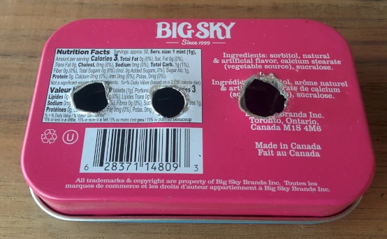
Step 3 - Install the two F-Connectors in the 3/8” holes and the power barrel connector. Tighten each.
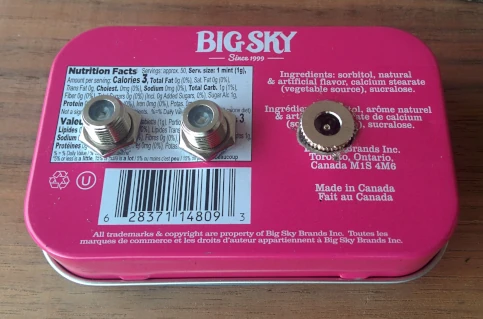
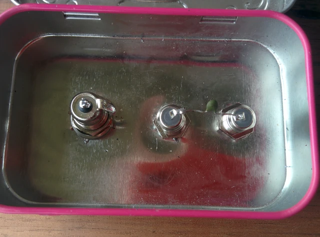
Step 4 - Solder a 1nF capacitor between the two F-Connectors.
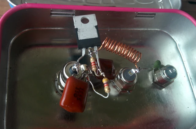
Step 5 - Cut the centre leg of the LM317 short and install it upside down with the left pin soldered to the centre pin on the barrel power connector. Solder a 0.1uF cap between the input (LM317 left pin) of the regulator and GND. GND is the outer tab on the power barrel connector. Solder another 0.1uF cap between the output (LM317 centre pin) of the regulator and GND.
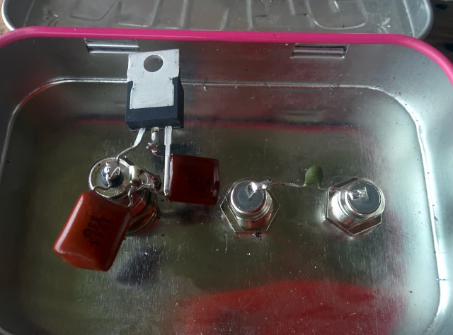
Step 6 - Solder a 1200Ω resistor between the LM317's centre pin and it's right pin. Solder a 4700Ω resistor between the LM317's right pin and GND. Solder the air wound inductor (aprox 150uH) between the LM317's output (centre pin or tab) and the closer F-connector. The AMP / Antenna will connect to this F-connector.
Step 7 - Solder the Diode between the LM317's output and the centre pin on the barrel connector. The diode's Cathode (black line) connects to the barrel connector.
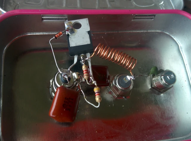
Plug in the wall power supply into the injector and check that the voltage is about 7v on the LM317's output. When the amp is connected to the injector, the voltage should be about 6.4v