This device and all information contained on this website is for educational purposes only. This device must be used in conjunction with any and all local, provincial and federal laws. It is up to the end user to comply with all legal guidelines, thus we are not and will not be held responsible for any misuse of this product or any damages that it may cause.
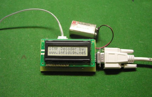
The DTMF decoder 2 is a useful tool used for decoding DTMF (Dual Tone Multi frequency) generated by telephones. The decoded digits are viewed on a 16x2 LCD screen. The DTMF decoder can be directly connected to a Serial port to view the digits in HyperTerminal on a computer. The decoder stores the last 234 received digits in EEPROM. The contents of EEPROM can be viewed on the LCD screen via two scroll buttons. Total power consumption is 12mA. The DTMF decoder has two inputs. A RJ11 jack for connecting to the phone line and a 1/8" audio jack for connecting to a scanner, tape recorder or other audio output device.
 The
DTMF Decoder 2 can be assembly by anyone with general electronic knowledge and soldering
skills.
The
DTMF Decoder 2 can be assembly by anyone with general electronic knowledge and soldering
skills.
A PCB layout is provided if one wishes to construct their own PCB. Simply print the file at 1:1 onto an overhead transparency. (Get the correct sheet for your type of printer) I used a kit by MG Chemicals (E-Sonic Search for 416-K) to produce my PCB. The provided PCB layout's smallest traces are 15 thou wide. Drill the holes for the headers at 40 thou. Drill the holes for the 20K POT, the buttons, and the audio jack at 35 thou. Drill the rest of the holes at 30 thou. Drill bits can be found a most hobby stores.
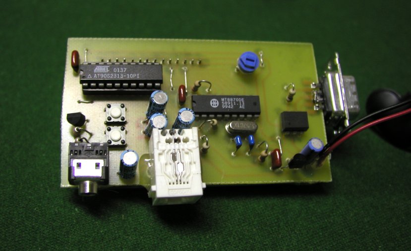
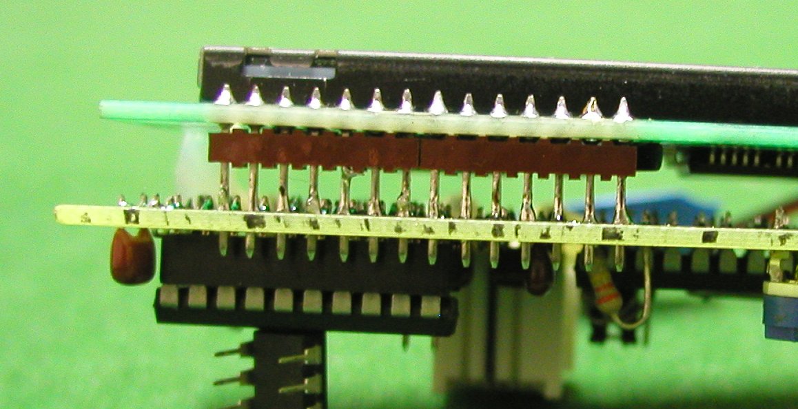
Review the schematic and parts placement diagram before beginning assembly for proper orientation of ICs and capacitors. Begin by installing the 7 jumper wires. Next solder in all the resistors and capacitors. Then solder in the buttons, the phone and audio jack, the 20K POT and the crystal. Solder in the 20 pin socket, ICs and 9v battery connector. Next solder the DB-9 connector to the end of the PCB. Short pins 7 and 8 on the DB-9 together by bridging them with solder. At this point, connect power and test the decoder for +5V between pins 10 and 20 on the 20 pin socket. Finally install the two, seven pin headers into the LCD (short side towards LCD). Solder the longer side of the headers into the DTMF decoder PCB. Attach the LCD and decoder together with hot glue or other means.
Feel free to email me with questions / problems at "drwho at infidigm dot net". I may not respond to all questions.
Programming the microcontroller is the next step. The micro is a AVR AT90S2313 made by ATMEL. An AVR socket programmer is required. Here is a list of programmers.
NOTE - If you are using the ATTINY2313, set the Fuse setting "external oscillator, 3-8 Mhz, 64mS startup time". Make sure that the Fuse setting "Divide clock by 8" is NOT set.
NOTE - Rev 1 and rev 2 software are interchangeable in both rev 1 and rev 2 of the decoder.
Only read this section if you wish to modify the program!
The program is written in C. It consists of one C file and was written to be complied under the free AVR-GCC C compiler (WinAVR 3.4.3 February 14, 2005). Read the beginners guide to learn how to install GCC. Once you have GCC working, download the Project Files for Programmers NotePad. and unzip them to a directory of your choosing. Run Programmers NotePad ( /WinAVR/pn/pn.exe). In PN go "File-->Open Project(s)" and select "dtmf2.pnproj" in the directory where you unzipped "dtmf2.zip". Open "dtmf2.c by double clicking on it. Click "Tools-->Make All" to test the Compiler. The program is well documented and self explanatory.To use the DTMF decoder, simply connect it to a 9V battery and the phone line. The DTMF decoder will accept ISOLATED DC voltages from 7 to 20 V for power. Upon power up the Message "DTMF decoder by www.infidigm.net" appears on the LCD screen. The message will remain there until a DTMF digit is received or a scroll button is pressed. If a DTMF digit is received while scrolling through EEPROM, the LCD screen is restored and the digit is appended to the end of the line. The LCD will auto scroll at the end of each line. Their are two scroll buttons, UP and DOWN. They will shift the last 234 digits through the LCD screen 13 at a time. UP will move towards the oldest received digit while DOWN will move towards the most recently received digit. Remember to set the 20K pot for LCD CONTRAST adjustment.
To connect the DTMF Decoder to the computer use a 'straight-through' DB9 pin serial cable. (Male on one end, female on the other) The connection to the computer is electrically isolated by the 4N25 Opto-isolator. (This is necessary so the phone line isn't shorted out to earth GND) The connection is TX only. This means that the information can only be sent from the DTMF decoder to the computer. Open HyperTerminal and setup a new connection for the appropriate COMM port. Set BAUD to 9600 8-N-1. Go into ASCII setup and make sure "Append line feeds to incoming line ends" is checked.
Upon power up the DTMF decoder will send the message "DTMF Decoder by www.infidigm.net" to HyperTerminal along with the last 234+ received digits from EEPROM. Every time a DTMF is received, the decoder will send the digit to HyperTerminal.
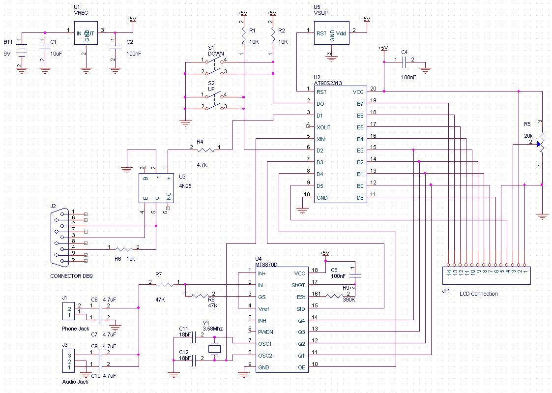
NOTE - The sensitivity of the decoders chip can be adjusted by changing R7 and R8. Where Av = R8 / R7. The schematic shows Av = 1
The list includes parts for the DTMF Decoder. All part numbers are for Digikey unless their is a link to another supplier.
| Quantity | Value | Description | Digikey Part No. | Component |
| 1 | 78L05 | +5V Regulator | 296-1365-1-ND | U1 |
| 1 | MCP120 | Supply Supervisor | MCP120-450DI/TO-ND | U5 |
| 1 | AT90S2313 | Microprocessor | AT90S2313-10PI-ND | U2 |
| or | Alternative Micro | ATTINY2313-20PI-ND | U2 | |
| 1 | MT8870DE | DTMF Decoder | E-SONIC | U4 |
| 1 | 4N25 | Opto-isolator | 160-1300-5-ND | U3 |
| 1 | 10uF | Dielectric | P10316-ND | C1 |
| 4 | 4.7 uF | P1199-ND | C6,7,9,10 | |
| 3 | 0.1 uF | P4525-ND | C2,4,8 | |
| 2 | 18pF | P4840-ND | C11,C12 | |
| 1 | 4.7K | 1/4 Watt | 4.7KQBK-ND | R4 |
| 3 | 10K | 1/4 Watt | 10KQBK-ND | R1,2,6 |
| 2 | 47K | 1/4 Watt | 47KQBK-ND | R7,R8 |
| 1 | 390K | 1/4 Watt | 390KQBK-ND | R9 |
| 1 | 20K POT | Vertical POT | 36G24-ND | R5 |
| 1 | 16x2 | LCD | 73-1025-N | LCD |
| 1 | RJ 11 Jack | CCM9000-ND | Phone | |
| 1 | 1/8 Audio Jack | CP-3543N-ND | Audio | |
| 1 | 9V Connector | BS6I-HD-ND | Batt | |
| 1 | 20-pin Socket | A9420-ND | ||
| 2 | Push Buttons | P8006S-ND | S1,S2 | |
| 2 | 0.1" | 7-pin Header strip | WM4005-ND | |
| 1 | 3.579545 Mhz | 3.58 Mhz Crystal | 300-6001-ND | Y1 |
| 1 | Female | DB9 Connector | A2047-ND | DB9 |
DTMF decoder Schematic
PCB Layout (Mirror image)
Parts Placement
All Program Project Files.
C Source Code
Hex file for AT90S2313
Hex file for ATTINY2313
AT90S2313 Data Sheet
(Microprocessor)
MT8870DE Data
Sheet (DTMF Decoder)
LCD Data Sheet